Sstc Driver
The Micro SSTC. Page created on 11/28/03. Here is a nice simple project that is incredibly simple compared to a typical SSTC and will work well with small high.
Class E PLL SSTC. A small Tesla coil will have a high resonant frequency, making conventional driving techniques difficult. What were once low capacitances suddenly.
The SSTC 1.0 is an incredibly simple Tesla coil that is an excellent choice for both beginners and seasoned enthusiasts. The small coil produces output arcs up to 2.0 in length, and easily illuminates fluorescent and neon lights due to the electric field it creates. It also features a self-resonant feedback circuit which tunes the coil automatically. No need to spend time tuning and re-tuning your coil. With just a single press of a button, this Tesla coil snaps right into life.
This kit is specially designed for students and schools, especially science projects. Coupled with the Wireless Energy Demonstration Kit, it is an excellent demonstration piece for showing the principles of wireless energy transfer.
We now also sell a Wireless Energy Demonstration Kit that is compatible with the SSTC 1.0 coil.
Click here for SSTC 1.0 Instruction Manual Rev 3 PDF - For SSTC 1.0 PCB boards marked SC2071- or SC2071A
Click here for SSTC 1.0 Instruction Manual Rev A PDF - For SSTC 1.0 PCB boards marked SC2071B
Click here for SSTC 1.0 Instruction Manual Rev B PDF - For SSTC 1.0 PCB boards marked SC2071B - Latest Version
Click here for the SSTC 1.0 Heatsink Template PDF - Be sure to print this out 1:1 on your printer. After printing, be sure to measure the dimensions with a ruler to ensure the template printed 1:1.
Features:
- Produces up to 2 Output Arcs
- Tested to 800kHz
- Self-Resonant Design Doesn t require tuning
- Strong electric field lights up fluorescent and neon lights with ease
- Excellent SSTC for a beginner or school science project
79.99
FALL SALE.
SSTC 1.0 Board Kit
Printed Circuit Board and Board Mounted components
Includes Aluminum Heatsink
Does not include Power Transformer or Tesla Resonator
Note: Heatsink will come with a 1:1 paper template and must be drilled by the customer
99.99
Complete SSTC 1.0 Kit
Includes Printed Circuit Board and all components including Power Transformer, Heatsink, and Tesla Resonator Kit
54.99
Wireless Energy Demonstration Kit for SSTC 1.0 - Complete Kit
Includes SSTC 1.0 Receiver Resonator Coil, PCB, Components, and Pri/Sec Wire
Available Now.
Please note that this kit will only work with our SSTC 1.0 Kit
19.99
SSTC 1.0 - Schematic Only 11x17.
Loneoceans Labs first Musical Tesla Coil
Project Esmeralda
8 x 3 Secondary - 60n60 halfbridge at
400VDC - Fiber Optic Analog Music Controller - 19 Sparks
Index
After a long hiatus building Tesla Coils, I m back again to work
on something new. I built a few tesla coils from 2003 to 2005, including perhaps Singapore s most powerful homebuilt
Tesla Coil 2. At this time, the hobbyist Tesla Coil
community was ushering a new era of Tesla Coils powered by power semiconductors
instead of spark gaps. These electronic, or Solid State Tesla Coils
SSTC were probably the first
major innovation since the original spark gap Tesla Coil invented by Nikola Tesla. Only a
handful of pioneers had the electrical know-how and skill to tread into
unfamiliar territory. It was then when I decided to build one for myself. I came
up with a design and procured components to being my first SSTC back in 2005. Yet
facing heavy school commitments and a lack of time, the project was put on hold until now.
Today 2011, SSTCs have seen major innovations evolving into
several variants including the popular Double Resonant Solid State Tesla Coil DRSSTC.
This page serves to document the design and construction of Loneoceans Lab s
first Solid State Tesla Coil. I understand that
the transition from Spark Gap Tesla Coils SGTCs to SSTCs is a fairly large
jump especially for those who do not have background in electrical engineering. I
hope this page along with other pages in the future will be able to serve as a
good introductory page to the workings of an SSTC, and to show the process as to how
I built my coil.
At time of writing, I do not know of any other SSTC in Singapore, and may be
the first of it s kind in my little sunny country. Thank you for visiting my page and if you have any questions,
wish to share your projects, or feel that my projects have inspired you in one
way or another, feel free to email me at loneoceans at gmail dot com.
Update March 2012 - SSTC 1
is now complete and now plays music.
1. Introduction
2. Design
3. Construction
4. Results Media
5. Useful Links
While the initial goal of this project was to learn about the
basic workings of a SSTC before embarking on a DRSSTC, SSTC 1 performed
spectacularly and can be modulated via fiber-optic in a variety of ways, from
producing sword-like spiral sparks to playing music via an analog stereo input.
Solid State Tesla Coil 1 plays Harry Potter.
For more videos and images of the coil in action, please scroll down to
Results Media.
Early Sept 2011
Introduction
This story begins in 2005. After having built several successful
Spark Gap Tesla Coils, I had planned to embark on some Solid State coil work. In fact, I had already purchased all the necessary components for a simple half-bridge SSTC. I had bought a nice heat-sink, a pile of TO-247 IRFP460 500V 20A MOSFETs as well as the required logic circuitry components, and even had a nice toroid made of a
styrofoam-doughnut. Unfortunately, lack of time, school commitments and other
various reasons lead to the project being shelved.
I m still in school and daily work isn t getting any easier, but I now have access to a reasonably well-stocked workshop, and have since
saved up a little bit of money. I decided it was time to get re-started
on the project. So at the beginning of this year s academic semester in September 2011, I decided to build my first SSTC. This page serves to document the initial design goals, project construction, and ultimately characterization and
documentation.
Project Goals Early Sept 2011
This will be a small coil. Small means more portable, more
manageable, and possibly cheaper. However, small does not mean weak. After
reading up on SSTCs people have built over the internet, I came up with a few
manageable and challenging but not overly optimistic goals for the project. I
will refer to these guidelines throughout the project. If you are building your
own SSTC also, it is definitely good to figure out a list like this.
- Use a 3 secondary of a winding height around 7 to 8
- Maximum power input of around 1000W
- Be reliable
- Be beautiful and well constructed
- Be as compact as possible while still being easy to maintain transportable via a
bagpack
- Use a half-bridge of 60n60 mini-brick IGBTs
- Controlled via fiber-optic
- Capable of Audio Modulation
- NOT be a DRSSTC this will be my next project.
- Be a great learning experience
- Not cost too much money
- To be completed in a reasonable time frame
- Capable of good-looking sparks, preferably over a foot long
- Run off 120VAC, and when I return to Singapore, be able to run it on 240AC also
For the first time, this coil will use green-enamelled magnet copper wire for the secondary.
Therefore, this project will be named Project Esmeralda, a.k.a SSTC 1, to signify the
emerald secondary. One interesting aspect of the coil will be the ability to run on dual line voltage,
120 or 240VAC. Also, it will feature a nice polycarbonate enclosure, and be
illuminated with LEDs.
With these goals in mind, I began the project,
Design
The design of the SSTC can be basically split into: 1 The Logic Control Circuit 2 The Power Circuit 3 The Interrupter 4 Physical construction and others. This section explains my design choices, as well as what I have learned through the progress of this project.
Update: Upon popular request, I decided to write a
reasonably comprehensive Guide to Building a SSTC for beginners, which I
tried to describe the workings and design of a basic SSTC through a
build-process. See my SSTC 2 page here. It covers
the basic operation and electronic workings in much more detail than
this page 2012 .
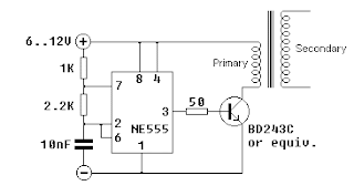
1. Driver Logic Control
The driver is perhaps the most important part of the
SSTC. The game plan for the driver: to create suitable signals to turn
the switching bridge in this case, a half-bridge at the correct
frequency. Being my first SSTC, I came up with a basic driver with the
help and advice from Rob Bryon and Steve Ward. Many thanks to them. In this
case, I designed the schematic with the following goals in mind:
To be essentially self-contained with the following I/O
ports
- 12V DC Input from a 12V DC adaptor
- 12V DC Fan Header output for cooling fan
- 2 Pin output for Gate Drive Transformer more on this later
- 3 Pin output for FB142-ND Fiber Optic Receiver
- 1 Pin output for the Antenna
Be contained on a small circuit board
The resulting driver is very simple and compact, using
only three ICs - two 9A Mosfet Drivers from Texas Instruments and one
74HC14 inverter. Let s talk about how the driver operates.
Power Supply
There are two low-voltage rails in the circuit. 12V is
provided by a regulated switch-mode DC power supply which powers the
cooling fan and provides the voltage for the Mosfet gate driver chips.
The 7805 IC regulates a 5V line for the rest of the logic ICs. The LED
12VLite turns on when the power supply is switched on.
Logic Circuitry
The gate drive transformer which supplies the switching
signals to the MOSFETs/IGBTs is driven by the UCC Mosfet Drivers. One of
them is inverting. In order to prevent the entire circuit from running
continuously, the circuit is enabled turned on or off via a signal
from the interrupter see below. The Interrupter basically sends
1-bit signals via a fiber optic cable to the Fiber Receiver FD142 same
as IF-D96F, which is an active low. When there is light in the fiber
optic, the receiver outputs logic 0 to the 74HC14. The 74HC14 is an
inverting chip with 6 inverters on it. It basically converts a logic 1
to a logic 0 and vice-versa, and cleans up the signal in the process.
When there is no signal from in interrupter, the FD142
outputs 5V logic 1 to the inverter one of the inverters of the
74HC14, in the schematic, pins 1 and 2. The signal is inverted to a 5
logic 1, which goes to the Enable gate of the UCC3732x drivers. To get
some feedback so I know the circuit is running, RX_LED is connected to
the same pin so it turns on when a signal is sent. When the gate drivers
are enabled, a short pulse is sent by the inverting UCC, causing the
coil to begin oscillating. This oscillating electric field is picked up
by the wire antenna a voltage is induced in it.
The oscillating signal is clamped by the 1N5819 or also
suitable 1n60 germanium diodes which clamp the voltage to 5V and GND,
and is sent as input through two inverters just to clean up the
signal into nice square waves. Then it is fed into the input of the gate driver chips. Because
they are an inverting pair, they work in opposition, producing a 12 to -12
24Vpp square wave across our Gate Drive Transformer.
The Gate Drive Transformer is a small ferrite core wound
by hand and is a fantastic way to isolate the gate drive signals to each
of the transistors. It is important to make sure that the GDT core is of
a suitable material, and can be tested by doing a test winding of two
wires, one connected to a signal generator Square wave and the other
to a scope to see the output. In this case, the two outputs of the GDT
are connected in inverse across the two IGBTs, so they switch on and off
correctly in opposition. And this is how the gate driver works.
2. The Power Circuit
Unlike a Spark-Gap Tesla Coil SGTC, a SSTC does not use a spark gap to switch current into the primary coil. Rather, it uses power semiconductors such as MOSEFETs Metal Oxide Semiconductor Field Effect Transistor and IGBTs Insulated Gate Bipolar Transistor. Despite great advances in technology, these semiconductors still take a lot of beating in the extremely high pulse currents
encountered, frequently running from a few hundred amps to a few thousand. The purpose of the logic circuit is to figure out how to switch these transistors to maximize their efficiency, reduce heating, and increasing their life-span. These transistors are
after all, one of the most expensive and most crucial parts of any SSTC. Fortunately, a lot of hardworking and passionate tesla-coilers have tried a variety of these power transistors. In choosing the suitable transistor for my coil, I did a reasonably comprehensive search of the different transistors and evaluated
their data-sheet specs, known performance, and cost.
Most IGBTs and MOSFETs of these power ratings come in either the standard TO-247 flat package or the popular
but expensive SOT-227 MiniBloc package. Often many of the same transistors come in both packages with equal ratings, but the SOT-227 package is preferred for its better heat dissipation characteristics and known toughness.
I decided to try a half bridge of 60N60C2D1 IGBTs to start with.
Name
Package
Volts
Current
Diode Recovery
Digikey Price
Known Performance
IXGN 60n60c2d1 HiPerFast IGBT
SOT-227
600V
60A
35ns
19.71
At least 3-foot at 400V bus on a 12 x 4.5
secondary half bridge; or 1.5m with a full bridge on 24x5.5
secondary at 700A
IXGN 40n60 IGBT
TO-247
75A
n/a
11.54
Well known excellent performance
HGTG 30n60b3d IGBT
32us
7.59
3-feet spark in full bridge of DRSSTC
Fairchild 60n100d IGBT
1kV
1200ns
Slightly slower than the competition
IRFP460 Powermesh MOSFET
500V
20A
480ns
6.28
Used commonly in small SSTCs
IRFP 260 MOSFET
200V
46A
390ns
6.70
3. The Interrupter
This SSTC will feature two different forms of power
modulation - through a basic and well established 555 interrupter
circuit, and second via a ATMega microcontroller producing musical
tones. I later build an analog musical controller for this coil which
worked very well and receives input from a 3.5mm stereo input.
4. Physical Construction
One of the main goals I had set for this coil was durability and portability. The design of the coil was to be elegant and modern, and yet small enough to fit into a large backpack.
Construction Log
This section logs the construction of Tesla Coil Esmeralda. This is my first Solid State Tesla Coil, and I decided to construct it in a modular form. I have therefore made this log into a few sections:
1. The Secondary Coil
2. Foam Torus
3.
Interrupter
4. Half Bridge
5. Bridge Driver
6. Enclosure
28 Sept 2011
Over the past few weeks, I have been gathering a list of components I plan to use, while trying to keep within my tight budget. I hope to make an order to digikey soon and get all the components at once. Most of the work has been in settling on a design for the coil. I had
initially planned to use a half-bridge of IRFP-460 MOSFETs because I had some of them lying around. However, I eventually decided to work on the more robust 60n60 fairchild IGBTs.
Today was a good day. In particular, I would like to thank MWS Wire Industries for kindly sponsoring 1600 feet of AWG30 Single PN-155 Green copper magnet wire for my project as a free sample. Also, I cycled to the Metropolitan Pipe and Supply Company today in an attempt to find 2.5 -diameter SCH40 PVC. It seems that most hardware shops stock only 3 or 2. These are inconvenient because they have an other diameter of 3.5 and 2.5 respectively, while the 2.5 pipe has an OD of 2.875, as per my design specifications. The people there were very understanding and gave me a foot half length for no cost. With these two components, I have most of what I need to complete my secondary coil.
30 Sept 2011
The wire has arrived. Take a look at how beautiful it is. The quality of the wire has completely surpassed my expectations and I have to thank MWS Wire Industries. The next best I could find are on ebay. Fortunately, they are not
particularly expensive. In addition, I have made an order on Digikey and hope it will arrive soon. Other people I want to thank include Bayley Wang who kindly donated a very nice full-copper heat-sink with a nice and powerful blue fan. This heat-sink will accept the two IGBT mini-bricks. The full-copper construction and powerful fan should provide equivalent cooling as a much larger static aluminium heat-sink. I also have managed to acquire a large Mallory 2500uF 450V capacitor 253J at full charge, 525V surge, as my bus capacitor. It is fairly large and places a lower-limit of my tesla-coil dimension.
Looking forward to begin construction. Meanwhile, I can begin sketching up my PCB for the logic and drive circuit of my SSTC.
08 Oct 2011
The Secondary Coil
With the wire and pipe in hand, it was time to start making the secondary coil. I ve wound several secondary coils already so this one should not be any more difficult. But before I can begin winding the coil, I ll first need to make the end caps. This will serve both as an aid for winding the coil to keep the pipe centered on a rod, and also to serve as a mounting structure. I quickly machined two end caps using some junk plastic stock lying around I m not sure what material it is but it seems like UHDPE on the lathe.
As you can see, part of the cap goes inside the pipe and is secured via three nylon screws. A hole directly through the centre will also accept another plastic bolt for mounting one end of the secondary coil to the enclosure and the other end to the topload. With this completed, I began winding the coil.
30AWG is not particularly thin, nor is my secondary coil very big measuring 2.875 in diameter,
so winding took just about an hour to complete. With about 8 inches of winding, that s just about 800 turns of wire. As you can see from the photographs, I taped the coil down at regular intervals as I wound it by hand. Once done, I secured the ends with one round of black electrical tape. To complete the coil, I varnished it with three layers of Polyurethane varnish. Any sort of polyurethane works well, but be sure to let each layer dry completely before applying the next layer. I found several thin coats to work very well in my Tesla Coils. The secondary coil is now complete.
11 Oct 2011
The Toroid
The topload of the Tesla Coil serves as a capacitor for the secondary part of the Tesla Coil circuit. It s traditionally always been the shape of a donut for several reasons - one of which because it produces a very nice electric field around the coil making it less likely to hit the base of the Tesla Coil, and also because it looks cool. There are several ways to make the topload, including blowing up a tyre inner-tube and pasting aluminium tape over, or for more fancy coils, using a spun or stamped metal toroid. Being unable to afford a nice metal toroid, I decided to make my own.
I found some nice modeling foam lying around the lab and decided to make my own foam donut. The foam was not thin enough so I glued two layers together using 3M-Spray Glue Super 77, and cut a cylindrical block on the band-saw. I then mounted it on the lathe and spent the next half an hour carefully shaping the foam by hand using a rough metal file and sandpaper. This worked remarkably well. At this point, I should caution users that this method is potentially very dangerous so I do not recommend you trying it.
After a while, I finally got the shaped I desired. The final result is nice but not perfect
because I shaped it entirely by hand, but it should work. Now the foam is rather fragile and easily dented. Therefore I wrapped it with strips of duct-tape, and then covered it with aluminium tape. The tape was then rubbed smooth using a curved object resulting in a reasonably smooth toroid. The topload is now complete. The topload measures about 3 minor by 8 major diameter.
17 Dec 2011
The Optical Interrupter
The interrupter is an important part of a Solid State Tesla Coil of any type including DRSSTCs. The reason for an interrupter is simple. When powering the Tesla Coil, one is sending huge currents at high frequencies into the Primary Coil via the power transistors. Unfortunately, these transistors are usually simply unable to handle these large currents especially in DRSSTCs where the currents are in the order of several hundred amps for any extended period of time without exploding. In many SSTCs traditional design, it is possible to run them in Continuous mode, but this places a lot of stress on the components.
The interrupter is a small circuit that basically interrupts the operation of the coil. Instead of running
continuously, the interrupter acts as a sort of switch to turn the drive circuitry to the power transistors on for a short amount of time say several hundred micro-seconds, before turning it off for a few miliseconds and then turning it back on again. This allows the duty cycle of the coil to be varied from 0 to 100. In order to make my SSTC run more reliably, I built my interrupter using a simple dual-555 circuit.
The goal of this circuit is to drive a Fiber-optic LED, with adjustable on-times, and adjustable intervals frequency. This is easily done by using one 555 timer in Astable mode which produces a continuous stream of
rectangular pulses at some frequency, which feeds into another 555 run in Mono-stable mode, which at each triggering edge of the previous 555 signal, generates an output pulse of some duration the on-time. The frequency of the Astable 555 and the on-time of the Monostable 555 are easily adjusted by varying the associated capacitor and resistor values e.g. using a variable resistor.
In order to make the interrupter circuit nice and compact, I decided to, for the first time. , design and fabricate my own PCB. This turned out to be surprisingly simple to do and yielded very nice results.
Here s how I made my own PCB. First, I designed the circuit in Eagle, which is perhaps the most commonly used PCB designing software in the world. This turned out to be very straightforward to use, and I was able to get my first circuit drawn up in an afternoon. Then I routed a single-sided PCB board, and printed out the traces using a laser printer onto magazine paper.
It is important to use magazine paper - the kind which is somewhat glossy, very thin, and quickly turns soft when exposed to water. I then literally used a hot iron and ironed on the print toner facing the copper side of a blank PCB board onto the copper. The heat makes the printer toner re-bond onto the surface of the copper. In order to remove the paper, I then submerged the PCB into warm water and allowed it to soak until the paper was completely wet. Then it was simply a matter of scraping off the paper - the toner bonds surprisingly well to the surface of the copper. Finally, the board is etched in a Ferric Chloride solution until all the copper is eaten away. The black toner is removed using Acetone.
The result - a surprisingly nice home-made toner etching. It wasn t as clean as I had hoped for but I think it s not bad for a first attempt. I drilled holes carefully using a small drill press and a tiny carbide drill bit, and installed the components of the interrupter. Notice that I tinned all the tracks of the copper using solder to make it a bit more durable. Also note the use of 3-pin fan headers for connecting other components such as the 9V battery and the variable resistors.
I tested the interrupter and it worked flawlessly. Success. The whole circuit board was then
assembled inside a nice aluminium project box I bought from Radio-shack for 3. With the interrupter now complete, it was time to make the driver circuit which will interface with the interrupter via a plastic fiber-optic cable. This will allow me to control the operation of the coil safely at a distance with no risk of getting electrocuted since the fiber optic is entirely non-conductive.
more technical information to come.
18 Dec 2011
60n60 Half Bridge
The most common circuit used in Solid State Tesla Coils
for the main inverter for the primary coil is the Half Bridge - a variant of the classic H-Bridge. If you re unfamiliar with the
terminology, the goal of the Half Bridge is basically to generate a voltage of 0.5Vs to -0.5Vs across our primary coil, where one end of the coil is held at 0.5Vs between two capacitors in series, where Vs is the source voltage.
One end of the load an inductor in this case representing the primary winding is tied to a point between two capacitors to fix it at 0.5 Vcc. The other end is switched between the ve Vcc rail and the ground. I decided to use a Half Bridge instead of a Full Bridge to save components and to maintain simplicity.
more technical explanation to come regarding the bridges.
To keep the 60N60s nice and cool and happy., I mounted them onto a nice solid-copper heatsink. Notice the protection diodes, TVS diodes to protect the IGBTs from spikes. A 5.1 Ohm resistor was connected to the gates of the transistor. The gates of the bridge are driven via a Gate Drive Transformer, which is controlled via the Driver Board see next section.
22 Dec 2011
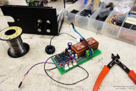
SSTC 1 s Driver and Control Board
This is perhaps the most critical part of the operation of the SSTC - the driver, which drives the gates of the power
transistors in this case, the two 60N60 IGBTs. This design is very simple and is derived from
Rob Bryon s SSTC which is based off Steve Ward s Micro SSTC. I modified the circuit slightly to suit my needs better.
Having had practice making my first PCB with the interrupter, I once again decided to design and fabricate my own SSTC Driver board. After a while in Eagle trying to fit everything together and routing the traces to fit on one-side, I was done. I found another type of paper which transferred toner better than magazine paper, and used it as my paper transfer sheet instead. This turned out beautifully. As you can see, the results are very nice.
As per above, I tinned the traces for durability and made sure that there were no unwanted shorts or open-circuits, and carefully installed all the components referring to a large printout I made for reference. After a busy night, the driver is complete. The driver is a simple antenna-based feedback, which goes perfectly into resonance by detecting the E-field from the primary coil. The driver uses a pair of UCC337321/22 Mosfet Drivers good for 9A to drive a Gate Drive Transformer at - 12V. This creates a 24V peak-to-peak square wave across a 18-turn 1-1-1 gate drive core. The two secondaries of the GDT are connected in opposite to each of the IGBTs, so that one is switched off when the other is on. It is very important to make sure they turn on and off in tandem otherwise a short is created across the primary capacitor, which will lead to an exploded half bridge.
Mar 2012
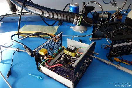
The Enclosure and Putting it all Together
With all the parts of the Tesla Coil complete, it s time to put it all together. I decided to make the coil durable enough to be transported back to Singapore, which meant it being tough enough to withstand being tossed around in a luggage bag. Therefore, I built the enclosure out of some nice Acrylic sheets I had lying around and four aluminium columns. The case is held together via four threaded rods.
I also made the footprint of the tesla coil exactly the size of a sheet of Letter paper, so the footprint measures 8.5x11. This fits all the components comfortably.
Above are photographs of the completed Tesla Coil. The primary coil comprises of 4 turns of multi-stranded AWG12 wire wrapped directly onto the secondary coil. A thick layer of soft PVC sheeting insulates the primary from the secondary. Also note the integrated 12V power supply the blue fan which cools the head-sink, and the large bridge rectifier which supplies directly to the large blue bus capacitor. The tesla coil accepts two IEC power cords -one for the 12V power supply and the other for the bus, as well as two switches, and a fiber optic receiver which connects to the driver.
With this, my first Solid State Tesla Coils is now complete. But will it work. Stay tuned to find out.
Project Esmerala - SSTC 1 is now complete.
Results - Photographs and Videos
13
Mar 2012
First light. After several months in the making, it s time to see if the coil will work or not.
I plugged the coil into a variac and slow turned up the voltage to about 40V, which the coil should begin producing some visible sparks. I set the interrupter to the lowest frequency and turned up the pulse-width to about 200us - and sparks appeared. I realized that my interrupter was not configured well with a normal SSTC operation, which will do better with a pulse width of a few mili-seconds instead of micro-seconds, so it s time to adjust the interrupter. This is easily done by changing the
capacitor of the Monostable 555.
Above shows the coil working at about 200us on-time per spark at about 170VDC on the bus. SSTC 1 is alive.
14
It s Pi Day today. It could not be a better day to test
SSTC 1. My original interrupter was set with a duty cycle that was too
small, which isn t the best configuration for a normal SSTC. I didn t
have any capacitors at hand to change the 555 interrupter circuit.
However, since the SSTC is optically triggered, I found that flashing a
light through the fiber-optic yielded excellent results.
Note that this cannot be done with a DRSSTC - only for
SSTCs which are capable of continuous operation usually referred to as
CW or continuous wave. The above photo show the coil
in action at 120VAC input. Note the very hot, fat sparks with a very
curious spiral / corkscrew formation. It s a fascinating shape.
16
I modified the interrupter to achieve good performance
with SSTC 1, by adjusting the circuit to allow for pulse widths around
1.5ms.
Above shows the coil running at 120VAC input with the
longer pulse widths. This allows sufficient time
for power to be transferred from the primary to secondary circuit. A bit
of salt was added to the breakout point which lends a yellow colouration
to the sparks as the sodium ionizes and glows. I m currently working on
a voltage doubler to bring almost 400VDC to the bus - what the coil was
originally designed to handle.
17
I then constructed a simple Voltage Doubler, which takes in
120VAC line voltage, rectifies it and doubles it up to 339VDC peak. This
is then fed directly to the Tesla Coil primary bus. My variac is able to
boost 120VAC to about 140VAC, so at full power, the coil sees roughly
395VDC peak, almost 400V. This is still within spec for all components.
I plugged in all in an turned on the interrupter
Video showing the workings and operation of SSTC 1.
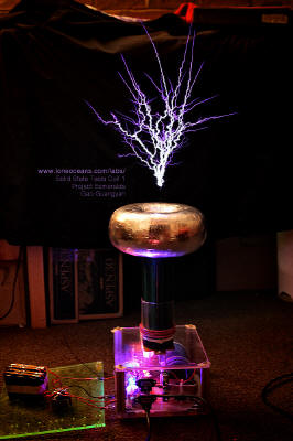
The results are spectacular, and more than I
could ask for. The coil performed admirably and reliably. I achieved
about a maximum of 19 spark to air about 48cm, which I am very
pleased with considering the 8 secondary coil length. This is almost
2.5x secondary length to spark length performance. A bit of
salt can be added at the tip of the breakout point see 3rd image above
which gives a mesmerizing yellow colouration to parts of the sparks.
Very cool.
Above is a video showing the coil in action. Notice how
the duty cycle and beats per second can be adjusted via the interrupter.
The voltage doubler box sits exposed outside and I do not recommend
this being done. I plan to put the doubler inside a grounded metal case
very soon.
25
Apr 2012
I installed new blue and green LEDs under my bed they
are of course wired up to dance with music - see my
LED lighting project here., and thought
it would make a fancy background for the coil. I also made a few small
changes to the coil, such as changing the LEDs at the bottom to a less
bright orange one so it doesn t saturate photographs. I also enclosed
the voltage doubler in a separate box so everything is less of a safety
hazard now.
I also tried changing the breakout point by adding a
very long wire. Mysteriously, the spark length shortened significantly,
but the results are good nonetheless. Very happy with how my coil is
running.
12
May 2012
My good friend Jonathan came to visit today.
We fired up the Tesla Coil and it performed admirably.
Here s a photograph left of Joanathan and the coil running at 120VAC and lighting up a
fluorescent bulb wirelessly, just as Nikola Tesla had intended it
to be. : The photo on the right is me operating the coil from
Jonathan s point of view.
June 2012
The photograph above shows the coil in my room in school
before it was packed up and shipped to Singapore. A few changes will be
required e.g. changing the 12V Power Supply to one that runs on 240VAC
before the coil is operational again.
August 2012
Update. Solid
State Tesla Coil 1 has been brought back to Singapore and now
lives here permanently with 240VAC without a pesky voltage doubler box.
Coil running at about 200VDC on the bus in Singapore after some
modifications
The coil has received some small adjustments since, and
now runs on a halfbridge of IXGH 60N60C2ND 75A 600V IGBTs in TO247-like
package, and I ve also replaced the capacitor with a more reasonable and
smaller array of four Nippon Chemicon 400V 470uF capacitors in series.
It now runs directly off 240VAC mains for about 380VDC on the bus with
the same excellent performance as before. The 12V power supply has been
replaced with a small iron-transformer power supply.
The above photographs show the details of SSTC1 and
compared to the newly improved
Tesla Coil 2. It s now time to progress to
DRSSTCs.
Some updated specifications
After taking into account insulation thickness of the
windings, I should have closer to 730 turns of wire on the 8 winding
length. With a 2.875 diameter secondary and a toroid measuring 3 x 8,
this puts the secondary resonant frequency around 465kHz or so. This
high frequency is not ideal for the IGBTs and in hindsight, I should
have made a lower-frequency setup. However, the high frequency probably
contributed to the sword-like sparks of the coil, and the big toroid
helped in increasing the brightness and power of the sparks.
Good Links
Here are some nice and very useful web pages.
More to come soon.
Back to main page
c Gao Guangyan 2016
Contact: loneoceans at gmail dot com.
Intro: Solid State Tesla Coil. A solid state Tesla coil is one of the kinds of Tesla coils available. It has several advantages over the more common spark gap tesla coil.
I know how a full bridge works and I knew it takes four; I was talking about a half bridge, like the kaizer SSTC I. but useing a single Mosfet, I tryed it and it.
Solid State Tesla Coil and Wireless Power. Version 1. Prefix: This is a Solid State version of a Tesla coil.
The SSTC 1.0 is an incredibly simple Tesla coil that is an excellent choice for both beginners and seasoned enthusiasts. The small coil produces output arcs up to 2.0.
A guide to how to build a SSTC the design and construction of the weekend coil SSTC 2.
The Mini SSTC. Page Created: 1/15/04. Updated 4/30/07. I built this small coil in about 1 day of work. Its small and relatively safe. It produces up to 7 of spark.